Structure
And Preponderance
- Rotary solenoid is designed based on the structures and principles
of push/pull solenoid flat type. Rotary solenoids are designed
as with 3 special oblique slots, and 3 bearing balls as media.
When
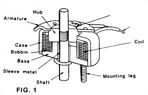 solenoid
pull, armature will lead the 3 bearing balls to move along the
oblique slots, resulting in rotary of certain angle. (FIG. 1) solenoid
pull, armature will lead the 3 bearing balls to move along the
oblique slots, resulting in rotary of certain angle. (FIG. 1)
- The oblique tracks are specially processed. We may therefore
get certain torque at every angle.
- Coil is covered by high permeability metal. The leakage of
magnet flux is very low.
- Due to small gap of rotary operation, by changing crank to
axial travel. Can obtain stronger force even with longer stroke.
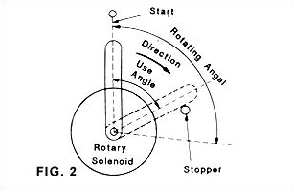
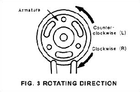
Rotating Direction And Angle
The angle and direction of rotary are decided by the case assembly
and tracks of bearing balls. Stopper is used to fix stop-position
to assure functions and characteristics. Refer to Fig. 2.
When release, The armature must return to point " 0 "
(Start-Position). (Please note, operation without releasing to Start-Position
is a cause of function failure.)
| Size\Angle |
25 |
35 |
45 |
67.5 |
95 |
| RT30 |
R.L |
R.L |
R.L |
- |
- |
| RT34 |
R.L |
R.L |
R.L |
R.L |
- |
| RT40 |
R.L |
R.L |
R.L |
R.L |
R.L |
| RT49 |
R.L |
R.L |
R.L |
R.L |
R.L |
| RT59 |
R.L |
R.L |
R.L |
R.L |
R.L |
| RT70 |
R.L |
R.L |
R.L |
R.L |
R.L |
| RT87 |
R.L |
R.L |
R.L |
R.L |
R.L |
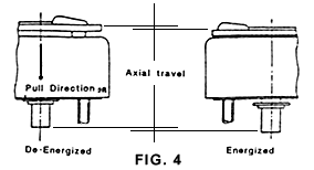
Axial Displacement Of Output Shaft
- The rotary solenoid is helically splinted, and when energized,
shifts its shaft a little in the axial direction to develop a
turning force.(FIG.4)
- Shown below is the size vs. shaft travel relationship to be
taken into account when coupling the output shaft with a load.
| TABLE 2 |
| SIZE |
30 |
34 |
40 |
49 |
59 |
70 |
87 |
Axial travel
(mm). approx. |
0.7 |
0.9 |
1.2 |
1.5 |
1.6 |
2.3 |
2.6 |
 Output
Shaft Arrangement And Accessories Output
Shaft Arrangement And Accessories
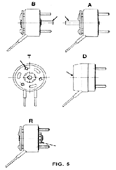
The rotary solenoids are classified as illustrated below without
regard to model designations. Make a choice to suit your installation
requirements. (FIG.5)
B: Shaft extended on the base side
A: Shaft extended on the armature side
T: Armature with tapped holes
D: Provided with a dust cover
R: Provided with return spring
General Characteristics
Insulation class:
E CLASS. ( however lead wire is A class)
Dielectric strength:
AC 1000V, 50/60Hz, 1 min. ( at normal temperature and normal humidity)
Insulation resistance:
more than 100MO on a DC 500V (at normal temperature and normal humidity)
Life standard:
2 million operations
Semi-long:
10 million operations
Long:
50 million operations
Points To Be Considered When Operation
- CONCERNING TEMPERATURE
The values of rotary solenoid coil data are based on ambience
temperature 20°C, and plating on standard heat sink.
And coil data is defined when rated operation, temperature rise
85? Max. In case of too high ambience temperature or too small
heat sink, please decrease duty cycle or operation voltage. Coil
temperature must not exceed 120°C
- CONCERNING PROCESS OF SHAFT AND ARMATURE TAP
When users process on shaft (Material: Stainless) and armature,
do protect metal cutting powder from adhering on slots of bearing
balls or release spring.
As life will be decreased seriously due to Mix of metal powder
and grease.
Methods Of Selection
To choose suitable rotary solenoids, please determine followings:
- TORQUE
Besides load, it's necessary to also consider variation of temperature
and voltage. Therefore please time load by safety coefficient
1.5x
- DUTY CYCLE
Besides on time and off time, please also note Max. on time.
- ANGLE OF ROTARY
To define required angle of rotary.
- DIRECTION OF ROTARY
To define required direction of rotary. Please note the direction
is defined when viewed from armature side.
- OPERATION VOLTAGE
To define coil input DC voltage.
Order Issuing
When order issuing, please define following 7 points
Example:
| SIZE |
ANGLE |
HEIGHT |
DIRECTION |
COIL NO. |
OUTPUT SHAFT ARRANGEMENT AND ACCESSORIES |
LIFE |
| RT40 |
25 |
E |
R |
29 |
A.B. |
STANDARD TYPE |
|

